


Technical Specifications
Operating Frequencies
486.4 to 639.9MHz
Block 19: 486.4 to 511.9 MHz
Block 21: 537.6 to 563.1 MHz
Block 24: 614.4 to 639.9 MHz*
*This block is targeted to be banned by the FCC for use within the US by July 13, 2020.
Frequencies Channels (per block)
256
Channel spacing
100 kHz (0.1 MHz)
Spurious & Harmonic Suppression: 37 dBc above 1 GHz
Frequency Stability: ±.001% (10 ppm) @ 25ºC
Temperature Stability: ±.001% (10 ppm) from -30º C to +50º C
Channel Selection: Momentary pushbutton switches, TUNE UP and Down
Compatibility Modes: IFB, Digital Hybrid Wireless; 400 Mode, 200 Mode, 100 Mode, Mode 3, Mode 6
Pilot Tone: 29.997 kHz IFB Mode, 32.765kHz; 200 Mode, 400 Mode step selected, 32.768kHz Mode 6
Modulation: FM, ±20 kHz deviation IFB & 100 Mode, ±75kHz 200 & 400 Mode, ±50kHz Mode 3 and Mode 6
Audio Frequency Response: 100 Hz to 8 kHz, ±1 dB, IFB MODE system response (see Rolloff), 30Hz to 20kHz ± 1dB, 200 & 400 MODE system response (see Rolloff)
Rolloff: Low frequency audio rolloff is Menu selectable for 3 dB down at 35 Hz or 50 Hz
Signal to Noise Ratio: 90 dB typical (“A” weighted)
RF Power Output: 250 mW (nominal)
Output Impedance: 50 Ohms
Audio Input Levels: 0 dBu for Line, RTS1 & RTS2, -10 dBu for Clear-Com, and -42 dBu mic dry inputs, +/-50VDC max
Audio Input Config: Balanced and Unbalanced, rear panel selectable for Line, Mic, RTS 1, RTS 2 and Clear-Com
Audio Input Impedance: Greater than 2 K balanced, greater than 1K unbalanced at any gain setting
Control Range: -18 dB to +24 dB (0 dB nominal center), software selectable
Audio Input Jack: Standard XLR female connector
Input Power: 12 to 14 VDC typical, 200 mA max; Max input range 6 to 18 VDC
Power Input Jack: Coax type, locking LZR RL26AE
Indicators: Backlit Liquid Crystal Display. Displays modulation meter, frequencies, modes, rolloff, audio level, and tuning groups
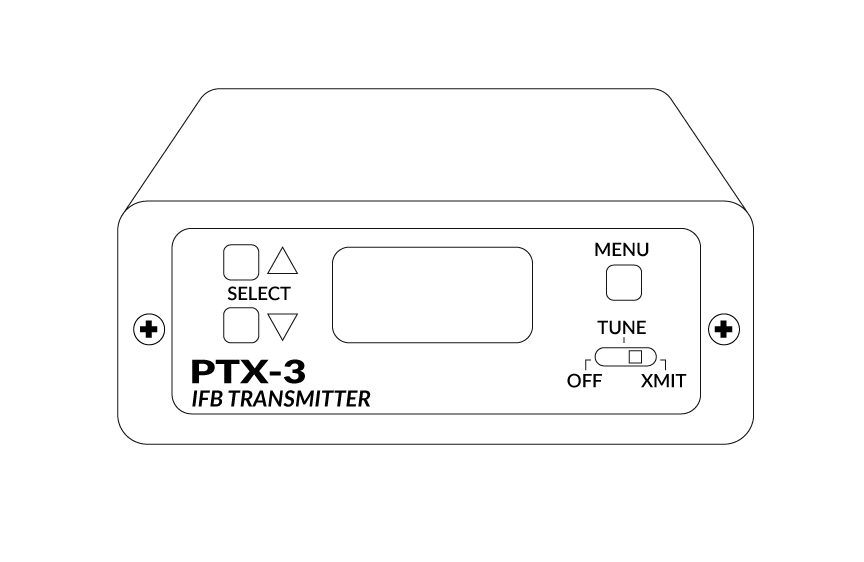
Front Panel Controls
MENU momentary pushbutton switch
Power OFF-TUNE-XMIT, 3 position slide switch
Select Up momentary pushbutton switch
Select Down momentary pushbutton switch
Rear Panel Controls: Input Mode Select, 4 section DIP switch
Weight
9oz
Size: 5.25” long (including connectors) x 3.25” wide x 1.25” high
Emission designator: 180KF3E
The T4 IFB transmitter is FCC type accepted under Part 74:470 –
608MHz and 944.1 – 951.9 MHz
The FCC requires that the following statement be included in this
manual:
This device complies with FCC radiation exposure limits as set forth for
an uncontrolled environment. This device should be installed and
operated so that its antenna(s) are not co-located or operating in
conjunction with any other antenna or transmitter. A separation
distance of at least 20cm (8 inches) must be maintained to comply with
the FCC Radio Frequency Maximum Permissible Exposure (MPE)
requirements.
Features and/or Benefits
Frequency Agility and Selection
The PTX-3 transmitter uses a synthesized, frequency selectable main oscillator. The frequency is extremely stable over a wide temperature range and over time. This flexibility significantly helps avoid interference problems in mobile or traveling applications.
A user-selectable low frequency roll-off can be set for 35 Hz or 50 Hz. The recommended 50 Hz default setting helps to remove wind and traffic noise, air conditioner rumble, and other sources of undesired low frequency audio. The 35 Hz setting offers a fuller range of sound in the absence of adverse conditions.
Rugged Construction
The PTX-3 is housed in a machined aluminum case with a tough electrostatic powder coating. The front and rear panels are anodized aluminum with laser etched engraving. The included antenna is a right angle, ¼ wavelength monopole with a BNC connector, constructed of polymer coated flexible steel cable.


Reviews
There are no reviews yet.